Turning Insert Nose Radius Explained: 0.2 vs 0.4 vs 0.8 vs 1.2 mm
Author : Surya makeyoueasy | Published On : 23 Oct 2026
Introduction
Choosing the correct carbide turning insert involves more than selecting its shape, grade, or chipbreaker. The nose radius also plays a major role in surface finish, cutting-edge strength, vibration, and productivity.
A smaller radius can help when machining thin components or making light finishing cuts. A larger radius provides a stronger cutting corner and can support higher feed rates, but it may increase radial cutting forces and vibration.
This guide compares 0.2 mm, 0.4 mm, 0.8 mm and 1.2 mm nose radii to help machinists select the right insert for CNC turning applications.
What Is a Turning Insert Nose Radius?
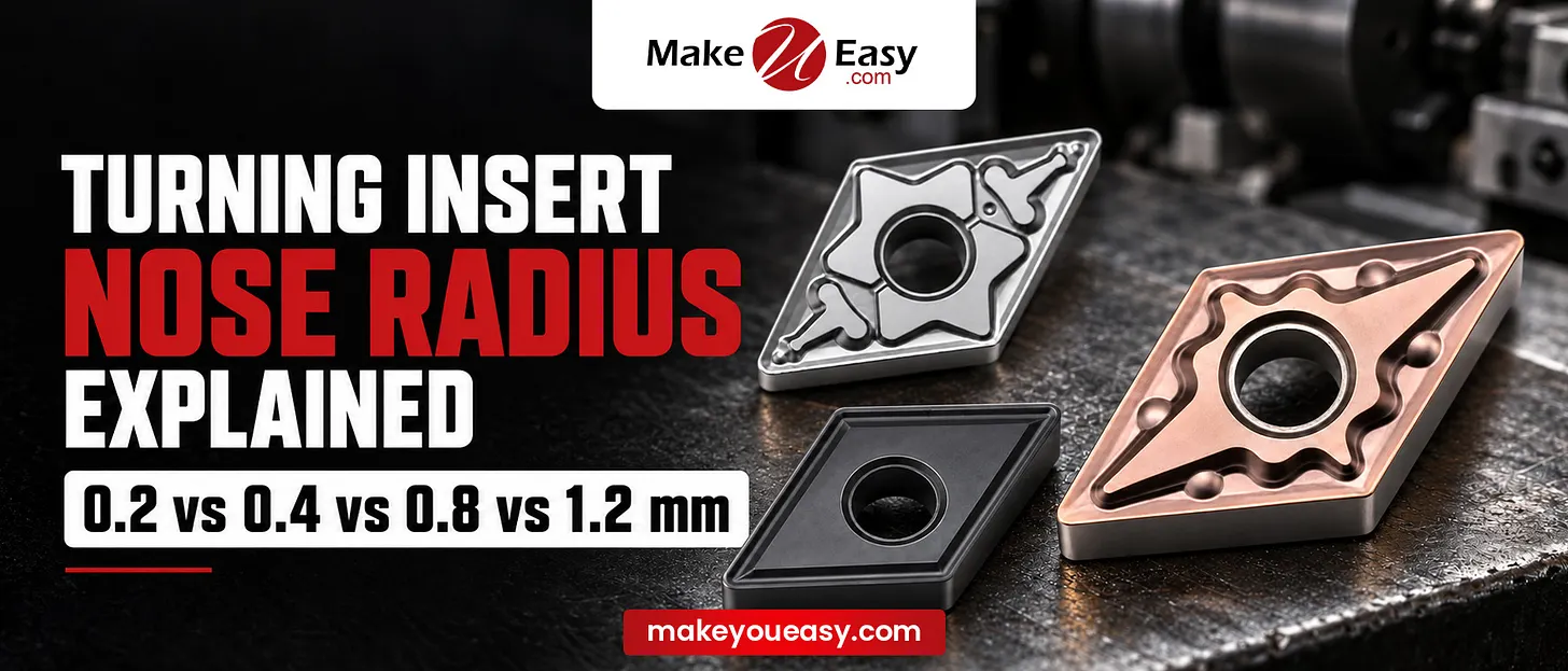
The nose radius, commonly represented by (r_varepsilon), is the rounded corner connecting the two main cutting edges of a turning insert.
It influences how the cutting edge engages the workpiece, distributes cutting loads, and generates the finished surface.
In many common ISO-style insert designations, the final two digits indicate the nose radius in tenths of a millimetre. For example, a code ending in 04 commonly indicates a 0.4 mm radius, while 08 indicates 0.8 mm. Always verify the complete insert designation against the manufacturer’s catalogue.
Types of Turning Insert Nose Radius
1. 0.2 mm Nose Radius: Precision Finishing
A 0.2 mm nose radius has a small cutting corner suited to light cuts and fine profiling.
Advantages:
-
Suitable for small features and tight contours.
-
Can reduce radial cutting forces in suitable applications.
-
Useful for light finishing passes.
-
Helps access smaller internal or external corner profiles.
Applications: Fine profiling, small precision components, delicate workpieces and selected finishing operations.
Limitation: The smaller corner generally has less strength and can be more vulnerable to chipping under heavy cutting loads.
2. 0.4 mm Nose Radius: Light Turning and Finishing
A 0.4 mm nose radius offers a useful balance for finishing operations where surface quality and controlled cutting forces matter.
Advantages:
-
Suitable for light finishing and semi-finishing.
-
Can perform well on slender components when the setup is stable.
-
Supports finer profiles than larger radii.
-
Offers a practical option for relatively shallow cuts.
Applications: Precision shafts, light external turning, finishing passes, and components susceptible to deflection.
Limitation: It may not provide sufficient corner strength for aggressive roughing or heavy interrupted cuts.
3. 0.8 mm Nose Radius: General-Purpose Turning
A 0.8 mm nose radius is a common general-purpose choice because it balances corner strength, surface-finish potential, and feed-rate capability.
Advantages:
-
Suitable for a broad range of general turning operations.
-
Offers greater corner strength than smaller radii.
-
Can support higher feeds when cutting conditions allow.
-
Provides a practical balance between finishing and material removal.
Applications: General CNC turning, semi-finishing, and suitable roughing operations on rigid setups.
Limitation: Increased radial forces compared with a smaller radius can cause vibration or deflection on slender workpieces and long tool overhangs.
4. 1.2 mm Nose Radius: Heavy-Duty Turning
A 1.2 mm nose radius provides a stronger corner for demanding cuts and higher feed rates when the machine and workpiece can withstand the additional cutting forces.
Advantages:
-
Stronger cutting corner for demanding applications.
-
Suitable for higher feeds and larger depths of cut within the insert’s recommended range.
-
Can provide a smoother theoretical surface at the same feed rate as a smaller radius.
-
Useful when edge strength is a priority.
Applications: Heavy external turning, roughing large components, and machining setups with good rigidity.
Limitation: Higher radial cutting forces may increase chatter, workpiece deflection or toolholder vibration, particularly on thin shafts and long overhangs.
Nose Radius Comparison Table
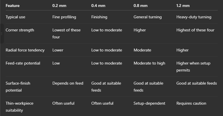
These are general tendencies, not guaranteed performance rankings. Insert grade, edge preparation, chipbreaker, feed rate, depth of cut, and machine rigidity all affect the result.
How Nose Radius Affects Surface Finish
Nose radius influences the theoretical surface profile left by the cutting tool. Under ideal turning conditions, the approximate relationship is:
[
R_a approx frac{f^2}{32r_varepsilon}
]
Where:
-
(R_a) = theoretical arithmetic average surface roughness in mm.
-
(f) = feed rate in mm/rev.
-
(r_varepsilon) = nose radius in mm.
For example, at a feed rate of 0.1 mm/rev, a larger nose radius produces a lower theoretical roughness value than a smaller radius, assuming the same ideal cutting geometry.
However, a larger nose radius does not automatically guarantee a better real-world finish. Vibration, tool wear, material properties, built-up edge, coolant and machine stability can significantly change the result.
How to Choose the Correct Nose Radius
-
For fine finishing: Use 0.2 mm or 0.4 mm for small profiles and light cuts.
-
For general turning: Consider 0.8 mm as a starting point when the machine, workpiece, and cutting parameters support it.
-
For heavy roughing: Consider 1.2 mm when greater corner strength and higher feeds are needed.
-
For slender shafts: A smaller radius may help reduce radial forces and deflection.
-
For internal turning: Check the minimum internal corner radius, boring-bar rigidity, and tool overhang before selecting the insert.
-
For final selection: Confirm the manufacturer’s recommended feed rate, depth of cut, chipbreaker range, and material grade.
Always match the radius to the actual operation rather than choosing solely on the basis of the surface finish you want.
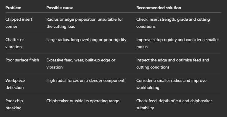
Common Nose Radius Problems and Solutions
Why Choose MakeYouEasy?
MakeYouEasy provides manufacturing professionals with CNC tooling information and resources to support informed machining decisions. Understanding insert nose radius, cutting-edge strength, and surface-finish requirements helps machinists select suitable tooling for their applications.
Explore machining resources at MakeYouEasy.com.
Conclusion
The correct turning insert nose radius depends on the balance between surface finish, cutting-edge strength, cutting forces, and workpiece rigidity.
-
0.2 mm: Fine profiling and light finishing.
-
0.4 mm: Light turning and finishing.
-
0.8 mm: Versatile general-purpose turning.
-
1.2 mm: Demanding cuts on sufficiently rigid setups.
Selecting the right radius helps improve machining stability, surface quality, and productivity while reducing avoidable insert failures.
FAQs
1. Which turning insert nose radius is best for finishing?
A 0.2 mm or 0.4 mm radius can suit light finishing, depending on the profile, feed rate, and required surface quality.
2. Is a 0.8 mm nose radius suitable for general CNC turning?
Yes, a 0.8 mm radius is a common general-purpose option when its cutting range matches the application.
3. Does a larger nose radius improve surface finish?
A larger radius can reduce theoretical surface roughness at the same feed rate, but vibration and other cutting conditions affect the actual finish.
4. Which nose radius is better for heavy roughing?
A 1.2 mm radius can provide greater corner strength for heavy roughing when the machine and workpiece setup are sufficiently rigid.
5. Can nose radius affect chatter during turning?
Yes, a larger radius can increase radial cutting forces and contribute to chatter in unstable setups.
Popular Search Keywords
turning insert nose radius, 0.2 vs 0.4 nose radius, 0.4 vs 0.8 turning insert, 0.8 vs 1.2 nose radius, carbide insert radius selection, CNC turning insert selection, nose radius and surface finish, turning insert cutting forces, carbide insert nose radius chart, CNC turning tool life
