Milling Insert Designations Explained: How to Read APMT, LNMU, SNMX, WNMU & Other Codes
Author : Surya makeyoueasy | Published On : 03 Nov 2026
Introduction
Milling inserts come in different shapes, sizes, geometries, and cutting configurations. Each insert carries a specific designation, such as APMT, LNMU, SNMX or WNMU, which helps identify its basic design and application. Understanding these codes makes it easier to select compatible inserts, identify replacement options, and avoid ordering mistakes. This guide explains common milling insert designations, their meanings, and how to read the complete insert code.
What Are Milling Insert Designations?
Milling insert designations are combinations of letters and numbers used to identify the geometry, dimensions, and configuration of indexable cutting inserts. Many common designations follow the ISO 1832 identification system, while certain milling insert families use additional manufacturer-specific coding.
A typical designation may communicate:
-
Insert shape and cutting-edge angle
-
Clearance or relief angle
-
Manufacturing tolerance
-
Fixing and chip breaker configuration
-
Insert size and thickness
-
Corner radius and additional geometry details
Understanding these elements helps machinists select the correct insert for face milling, shoulder milling, high-feed milling, and other operations.
1. Understanding the First Four Letters
The first four letters of many ISO-based insert designations identify important geometric characteristics.
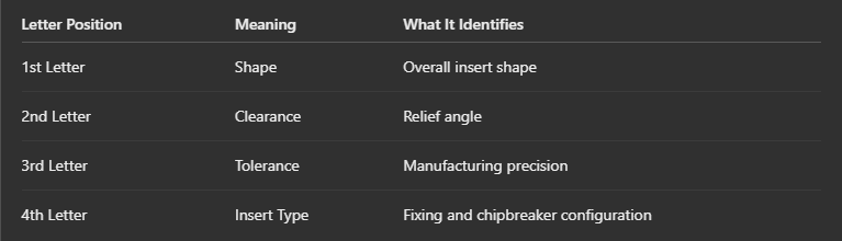
Common first-letter shape codes:
-
A – Parallelogram, 85°
-
C – Rhombic, 80°
-
D – Rhombic, 55°
-
S – Square, 90°
-
T – Triangular, 60°
-
V – Rhombic, 35°
-
W – Trigon, 80°
-
R – Round
Common clearance codes:
-
N – 0° clearance
-
P – 11° clearance
-
C – 7° clearance
-
E – 20° clearance
-
F – 25° clearance
The third and fourth letters identify tolerance and fixing or chipbreaker characteristics. Their exact interpretation should be checked against the applicable designation standard and manufacturer’s catalogue.
2. Common Milling Insert Designations Explained
Different insert families are designed for different machining operations. Here are some commonly encountered designations.
APMT Inserts
APMT inserts are widely used in square shoulder milling and face milling cutters. They feature a parallelogram-shaped geometry and are commonly available in positive cutting configurations.
Example: APMT 1604
-
A – 85° parallelogram shape
-
P – 11° clearance
-
M – Tolerance class
-
T – Fixing and chipbreaker configuration
-
16 – Insert size code
-
04 – Thickness code
The complete designation may include additional details such as corner radius, wiper geometry, cutting direction and chipbreaker.
LNMU Inserts
LNMU inserts are commonly associated with high-feed milling applications. Their geometry is designed to support high feed rates and efficient material removal at relatively low cutting depths.
They are available in different geometries and grades for various workpiece materials and machining conditions.
Always check the complete LNMU designation and cutter catalogue before selecting a replacement.
SNMX Inserts
SNMX inserts are commonly used in face milling applications. Many versions feature a double-sided square design with eight usable cutting edges, making them economical for suitable machining operations.
They are available in different geometries for general machining, medium cutting and roughing applications.
WNMU Inserts
WNMU inserts feature a double-sided trigon-shaped design. Compatible versions generally provide six usable cutting edges.
They are used in suitable face milling and shoulder milling cutter systems. Their compact geometry and multiple cutting edges make them useful for economical machining applications.
Important: These four-letter families identify broad insert types, not universal cutter compatibility. Always verify the complete part number, dimensions, grade and cutter pocket.
3. How to Read Milling Insert Numbers and Suffixes
Numbers and additional letters following the basic insert designation provide further information.
Consider the example APMT 160408:
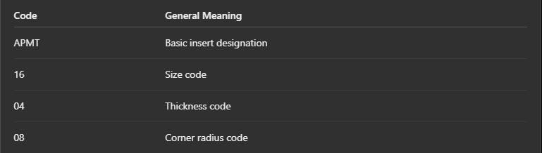
In this example, 08 commonly represents a 0.8 mm corner radius. However, the dimensional interpretation of size and thickness codes must be confirmed using the relevant insert standard or manufacturer’s dimensional chart.
Additional suffixes may identify:
-
Chipbreaker geometry
-
Edge preparation
-
Cutting direction
-
Wiper configuration
-
Carbide grade and coating
These suffixes can differ between manufacturers, even when the basic insert designation is similar.
4. Why Is Understanding Insert Designations Important?
Selecting an insert based only on its appearance can lead to compatibility and machining problems. Understanding the designation helps with:
Correct Insert Selection: Identify the required shape, size, and geometry for the machining operation.
Cutter Compatibility: Verify the insert dimensions, seating arrangement, and clamping requirements.
Improved Machining Performance: Select suitable cutting geometries for finishing, medium machining, and roughing.
Cost Management: Identify suitable replacement inserts and make better use of available cutting edges.
Reduced Downtime: Avoid incorrect purchases and unnecessary tool changes.
5. How to Select the Right Milling Insert
Before purchasing a milling insert, consider these factors:
-
Machining Operation: Identify whether the application involves face milling, shoulder milling, slot milling or high-feed milling.
-
Insert Geometry: Select the appropriate shape, clearance angle, and cutting-edge configuration.
-
Workpiece Material: Consider whether you are machining steel, stainless steel, cast iron, aluminium or hardened materials.
-
Cutter Compatibility: Match the complete insert designation with the cutter manufacturer’s specifications.
-
Grade and Coating: Choose a suitable carbide grade and coating based on cutting conditions and workpiece material.
The right combination of insert geometry, grade, and machining parameters helps achieve consistent performance and better tool life.
Conclusion
Milling insert designations provide valuable information about insert geometry, dimensions, and cutting configurations. Understanding common codes such as APMT, LNMU, SNMX and WNMU makes insert identification and selection easier. However, the complete designation and manufacturer’s catalogue should always be checked before purchasing or replacing an insert. Choosing the correct insert improves machining efficiency, supports consistent cutting performance, and helps control tooling costs.
Frequently Asked Questions
1. What does APMT mean in milling inserts?
APMT identifies a parallelogram-shaped positive milling insert family commonly used in shoulder and face milling.
2. What is the difference between APMT and APKT inserts?
Both are commonly used in shoulder milling, but their exact geometries and configurations can differ. Check cutter compatibility before selecting either type.
3. What are SNMX inserts used for?
SNMX inserts are commonly used in face milling and are available in double-sided square designs with eight cutting edges.
4. What are WNMU inserts used for?
WNMU inserts are double-sided trigon-shaped inserts used in compatible milling cutters for suitable face and shoulder milling operations.
5. Can different brands use the same milling insert designation?
Yes. However, identical basic designations do not automatically guarantee compatibility. Dimensions, geometry, grade, and cutter pocket specifications must be verified.
Popular Search Keywords
Milling insert designation chart, APMT insert meaning, LNMU milling inserts, SNMX insert applications, WNMU carbide inserts, ISO insert identification, indexable milling inserts, carbide insert selection guide, CNC milling cutter inserts, milling insert geometry
