Material Flow Considerations When Selecting Feeders for Furnace Charging Systems
Author : Star Trace | Published On : 30 Sep 2026
Material flow plays an important role in furnace charging. The charging system must move raw material from storage to the furnace in a controlled and consistent manner. If material flow is irregular, the furnace may not receive the required quantity at the required time.
Material Characteristics Come First
The physical properties of the material directly influence how it moves through a charging system.
Before selecting Feeders for Furnace applications, industries should review:
-
Material type
-
Particle or piece size
-
Bulk density
-
Shape
-
Moisture content
-
Surface characteristics
-
Flow behaviour
Metal charge materials can vary considerably in size and shape. The feeder should therefore be selected according to the actual material rather than a general assumption about the application.
Hopper Discharge Affects Material Flow
The feeder normally receives material from a hopper or storage bin. The hopper outlet needs to provide a suitable supply to the feeder.
If material builds up above the outlet or flows unevenly, the feeder may not receive a consistent load. This can affect the quantity being delivered toward the furnace.
For this reason, hopper dimensions and outlet arrangements should be considered together with the feeder.
A Furnace Charging Device works more effectively when the storage and feeding sections are designed as a connected system.
Feeder Dimensions Influence the Material Path
The width and length of the feeder determine how material travels toward the furnace.
A wider feeder may be required for larger material quantities, while feeder length depends partly on the distance between the storage point and furnace opening.
The equipment manufacturer should receive information about:
-
Required material flow
-
Available feeder space
-
Material size
-
Hopper arrangement
-
Furnace opening location
These details help establish an appropriate feeding configuration.
Electromagnetic Vibration Helps Regulate Movement
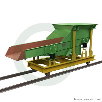
An Electromagnetic Vibrating Feeder uses controlled vibration to move material along the feeder tray.
The feeding action can be adjusted according to the required process conditions. This makes electromagnetic vibration useful for applications where the furnace needs a controlled supply instead of uncontrolled material discharge.
The required operating pattern depends on the furnace process and material characteristics.
Feed Rate Should Match Furnace Requirements
The charging rate should be considered in relation to the furnace operation.
If the required material flow is not established correctly, the charging system may deliver material too slowly or too quickly for the process.
The feeder selection should therefore begin with a defined feed requirement. The manufacturer can then consider the feeder size and operating characteristics needed to handle that flow.
For a Vibratory Furnace Charger, feed rate is one of the central factors connecting the feeder with the furnace process.
Material Size Can Change Feeding Behaviour
Charge materials with different sizes may move differently across the feeder surface.
Small granular materials can behave differently from larger metal pieces. Irregularly shaped material can also create a different flow pattern from uniform particles.
When searching for a Vibratory Feeder for Sale, industries should provide the expected material size range instead of describing the material only by its general name.
This helps the supplier understand the actual feeding requirement.
The Charging Route Should Be Kept Practical
The complete route from storage to furnace should be reviewed before selecting the equipment.
A practical charging route should consider:
-
Material storage location
-
Hopper discharge
-
Feeder position
-
Material travel distance
-
Feeder discharge point
-
Furnace opening
-
Required material entry position
This approach helps avoid selecting a feeder that does not fit the available installation arrangement.
Furnace Position Influences the Discharge Arrangement
The final discharge point is particularly important because material needs to enter the furnace at the intended location.
The feeder may need to be positioned at a particular height, angle or distance depending on the furnace configuration.
The surrounding equipment should also provide enough space for inspection and maintenance.
For Feeders for Furnace applications, the discharge arrangement should therefore be considered during the initial planning stage.
Consistent Flow Supports Production Operations
Furnace charging is often connected with a larger production process. Consistent material movement can help maintain a predictable charging routine.
The feeding system should be able to handle the expected operating cycle and material loading pattern.
An electromagnetic feeder can be incorporated into a controlled feeding arrangement where the material supply needs to be adjusted according to production requirements.
Operating Conditions Should Be Included in Feeder Selection
The environment around a furnace can differ from a normal material-handling area.
Heat, dust, operating frequency and available installation space should be communicated to the equipment supplier. These conditions can influence how the feeder is positioned and integrated into the charging system.
The manufacturer should understand the actual operating environment before finalising the equipment configuration.
Information to Share With a Feeder Manufacturer
Companies evaluating Vibratory Feeders India can prepare a simple application sheet before contacting suppliers.

