How to Choose the Right LNMU High-Feed Milling Cutter for CNC Machining
Author : Surya makeyoueasy | Published On : 22 Sep 2026

Introduction
Choosing the right LNMU high-feed milling cutter can improve material removal, machining stability, and cycle time in CNC milling. LNMU cutters use double-sided carbide inserts with a small entering angle, allowing high feed rates while keeping the axial depth of cut relatively shallow. However, the correct cutter depends on the insert size, cutter diameter, workpiece material, insert grade, machining operation, machine rigidity, and required feed rate. Tungaloy’s LNMU range, for example, includes different geometries for general-purpose, low-force, stainless-steel, and heavy-duty applications.
What Is an LNMU High-Feed Milling Cutter?
An LNMU high-feed cutter is an indexable milling system designed for high-feed machining with shallow axial depths of cut.
The small entering angle changes how cutting forces are transmitted into the machine. More of the cutting force is directed axially toward the spindle, which can help improve stability, particularly when machining with longer tool overhangs.
LNMU systems are commonly used for:
-
Face milling
-
Pocket roughing
-
Cavity machining
-
Ramp milling
-
Shoulder machining
-
High-volume roughing
-
Long-overhang applications
1. Choose the Correct LNMU Insert Size
The first step is matching the cutter body to the correct insert size.
Common LNMU systems include sizes such as
-
LNMU03
-
LNMU06
For example, Tungaloy’s LNMU03ZER-MJ has an insert width of 6 mm, thickness of 4.3 mm, effective cutting-edge length of 3.2 mm, and maximum axial depth of cut of 1 mm.
The larger LNMU06 family can provide a larger cutting edge and higher feed capability. One Tungaloy LNMU06ZER-MJ configuration has a 6 mm effective cutting edge, 7 mm thickness, four cutting edges, and a 1.5 mm maximum depth of cut.
Always match the insert designation exactly to the cutter pocket.
2. Select the Cutter Diameter
Cutter diameter affects productivity, cutting load, and the number of inserts engaged in the cut.
Smaller Diameter
A smaller cutter is useful for:
-
Compact components
-
Narrow pockets
-
Restricted machining areas
-
Lower-power machines
Larger Diameter
A larger cutter can provide:
-
Greater surface coverage
-
More cutting edges
-
Higher potential material-removal rates
-
More stable face milling in suitable setups
Choose the largest cutter that comfortably fits the component and machine without creating excessive spindle load.
3. Select the Right Insert Geometry
LNMU systems are available with different chipbreakers and geometries.
Tungaloy’s LNMU03 range includes:
-
MJ: General-purpose geometry
-
ML: Low-cutting-force geometry
-
MS: Stainless-steel geometry
-
MH: Robust cutting-edge geometry
It also lists UER versions with a low approach angle.
MJ Geometry
A good starting point for general-purpose milling where balanced cutting performance is required.
ML Geometry
Useful when reducing cutting forces is important, such as long tool overhangs or less-rigid setups.
MS Geometry
Designed for stainless-steel applications where cutting behavior and chip control require a dedicated geometry.
MH Geometry
A stronger-edge option for applications where edge robustness is more important.
4. Match the Grade to the Workpiece
The insert grade should match the material being machined.
Typical ISO material groups include:
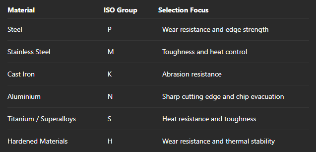
Tungaloy’s LNMU06 products demonstrate that grade selection can change the applicable material range. For example, AH120 is listed for steel, stainless steel, cast iron, hard materials, and superalloys/titanium, while AH130 is listed for steel, stainless steel, and superalloys/titanium.
Always use the manufacturer’s grade recommendation for the exact material and cutting condition.
5. Understand High-Feed Cutting
High-feed milling does not mean simply increasing feed rate while keeping conventional milling parameters unchanged.
The technique combines:
Small axial depth of cut + small entering angle + high feed per tooth
This allows the cutter to remove material efficiently while directing a large portion of the cutting force toward the spindle.
For example, published LNMU03 data from one manufacturer lists feed ranges of approximately 0.5 to 1.5 mm/tooth, depending on the material and cutting condition.
The actual feed should always be calculated from the manufacturer’s recommended cutting data.
6. Check Maximum Depth of Cut
LNMU high-feed cutters are designed around relatively shallow axial cutting depths.
Exceeding the recommended APMX can increase:
-
Cutting forces
-
Spindle load
-
Insert wear
-
Vibration
-
Edge chipping
For example, Tungaloy lists 1.0 mm APMX for its LNMU03ZER inserts and 1.5 mm for the referenced LNMU06ZER inserts.
Do not treat these values as universal for every LNMU cutter. Check the exact cutter and insert combination.
7. Consider Machine Rigidity and Tool Overhang
One major advantage of high-feed milling is that the force direction can help stabilize long-overhang applications.
However, excessive overhang still increases deflection and vibration.
For better performance:
-
Use the shortest practical tool.
-
Select a rigid holder.
-
Minimize cutter projection.
-
Check spindle and holder runout.
-
Secure the workpiece properly.
-
Monitor spindle load during initial cutting.
Low-force LNMU geometries can be useful when the machine or setup requires reduced cutting forces.
8. Choose the Right Number of Cutter Teeth
The number of teeth affects both productivity and required machine power.
More teeth can increase potential material removal because more cutting edges can engage during each revolution.
However, the machine must provide sufficient:
-
Spindle power
-
Torque
-
Feed rate
-
Chip evacuation capacity
For a lower-power machine, a cutter with fewer teeth may provide more practical chip space and reduce instantaneous load.
9. Check Coolant and Chip Evacuation
High-feed milling can generate large quantities of chips.
Poor chip evacuation can cause:
-
Recutting
-
Surface damage
-
Excessive heat
-
Insert wear
-
Chip packing
Use suitable air, coolant, or through-tool coolant depending on the workpiece and cutter design.
Some LNMU cutter bodies are specifically available with internal coolant capability.
LNMU Cutter Selection Checklist
Before purchasing, verify:
-
LNMU insert size
-
Complete insert designation
-
Cutter diameter
-
Number of teeth
-
Insert grade
-
Chipbreaker geometry
-
Maximum APMX
-
Recommended feed per tooth
-
Workpiece material
-
Machine spindle power
-
Toolholder type
-
Tool overhang
-
Coolant capability
-
Cutter pocket compatibility
Never select an LNMU cutter based only on insert shape. The insert, cutter body, grade, machine, material, and cutting parameters must work as one system.
Why Choose MakeYouEasy?
At MakeYouEasy, you can explore CNC milling tools and machining accessories for different industrial applications.
Relevant categories can include LNMU high-feed milling cutters, LNMU carbide inserts, face milling cutters, solid carbide end mills, boring tools, threading tools, and CNC tool holders.
Before purchasing, verify the complete cutter and insert specifications, especially insert size, geometry, grade, cutter diameter, pocket compatibility, and recommended cutting parameters.
Conclusion
Choosing the right LNMU high-feed milling cutter requires matching the cutter system to the material, machining operation, machine capability, and required productivity. Start with the correct LNMU insert size, then select the appropriate geometry, carbide grade, cutter diameter, number of teeth, and toolholder.
For stable high-feed machining, maintain a shallow axial depth of cut, use the manufacturer’s recommended feed and speed, minimize tool overhang, and ensure effective chip evacuation. With the correct combination, an LNMU system can provide high material-removal rates, stable cutting, efficient roughing, and reduced machining time.
Frequently Asked Questions
1. What is an LNMU high-feed milling cutter used for?
It is mainly used for high-feed roughing, face milling, pocketing, ramping, and other operations requiring high material removal with shallow axial cutting.
2. How many cutting edges does an LNMU insert have?
Many LNMU designs are double-sided and provide four usable cutting edges.
3. Can LNMU cutters machine stainless steel?
Yes, specific LNMU geometries and grades are available for stainless-steel machining.
4. Why is the depth of cut relatively small in high-feed milling?
The small axial depth works with the low entering angle to enable high feed rates while controlling cutting forces.
5. How do I choose an LNMU insert grade?
Select the grade according to the workpiece material, hardness, cutting speed, stability, and manufacturer’s application recommendations.
Popular Search Keywords
LNMU High Feed Milling Cutter, LNMU Milling Cutter, LNMU High Feed Inserts, LNMU Carbide Inserts, High Feed Milling Cutter for CNC, LNMU03 Milling Cutter, LNMU06 Milling Cutter, High Feed Milling Inserts, CNC High Feed Milling Tool, LNMU Cutter for Steel, LNMU Cutter for Stainless Steel
