Flexible Copper Busbar vs Rigid Busbar: Choosing for Your Panel Design
Author : Shekhar Chaudhary | Published On : 27 Aug 2026
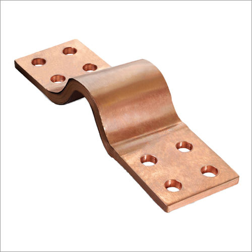
Every panel designer eventually hits the same fork in the road: cable or busbar? And if busbar, flexible or rigid? It seems like a small decision until you're three months into a project and realise the wrong call is adding hours to every installation or, worse, causing thermal issues nobody caught in review. Getting this right early saves a lot of pain later, so let's actually walk through how a flexible copper busbar stacks up against a rigid one and when each makes sense.
What a Busbar Actually Does
A busbar is a solid conductor (usually copper or aluminium) used to collect and distribute current inside switchgear, distribution panels, or industrial enclosures. Compared with cable, busbars offer lower impedance, better thermal behaviour, and higher current-carrying capacity for a given footprint. That's the whole appeal: less bulk, better performance, cleaner panel layouts. The question is just which form factor gets you there for your specific application.
Rigid Busbar (The Stable Workhorse)
Rigid copper bar has been the default in fixed installations for a reason. Its solid, one-piece construction gives it a slight edge in current-carrying capacity for an equivalent cross-section compared to flexible options, largely because of superior directional heat conduction. It's also less susceptible to physical damage during installation, which tends to mean lower long-term maintenance and a longer service life once it's bolted in.
The catch is customisation. Rigid bars are essentially bespoke; every bend, offset, and hole pattern has to be engineered and machined for that specific panel. Change the layout later, and you're often replacing the whole assembly rather than adjusting it. That's fine for substations, fixed distribution panels, and large industrial equipment where the geometry isn't going to change. It's a poor fit anywhere vibration, movement, or design iteration is part of the picture.
Flexible Busbar (Built for Movement and Tight Spaces)
Electrical bus bars in flexible form are typically built from multiple thin layers of laminated copper (or braided strands) wrapped in an insulating jacket, which lets the conductor bend and shape itself around obstacles rather than forcing the panel layout to accommodate a rigid bar. This matters enormously in EV battery packs, robotics, and compact distribution cabinets where every millimetre of enclosure space is contested, and vibration is a constant fact of life.
The practical upside shows up fast during installation: flexible busbar can cut the number of connectors needed dramatically and shorten install time compared with an equivalent rigid or cable-based layout, simply because it eliminates a lot of the custom bending and bracket work rigid bar demands. It also tends to need less ongoing maintenance no periodic torque checks the way bolted rigid connections require.
The trade-off is cost and, in some designs, current capacity. Flexible busbar generally costs more per unit of raw material than rigid bar, though the lower installation labour often offsets that over the life of a project. And while flexible designs can be engineered to carry very high currents in the right configuration, rigid bar still generally holds a modest edge in raw ampacity per cross-sectional area.
Sizing It Correctly: Where Most Mistakes Happen?
Whichever type you choose, sizing comes down to the same underlying physics: current through resistance generates heat (Joule heating), and if the cross-section is too small for the load, resistance climbs, heat builds beyond what the design can dissipate, and you end up with insulation degradation, rising contact resistance, and in the worst cases, arc flash risk.
Manufacturers typically publish ampacity tables relating cross-sectional area to continuous current rating, but real-world panel layouts (especially compact enclosures with limited airflow) need to be checked against actual temperature rise, not just the table value.
For flexible busbar specifically, the detail that separates a good design from a failure-prone one is controlled flexion: the bar needs to bend where the design intends it to bend, not at the terminal weld or the mounting hole, where repeated flexing there leads to fatigue failure over time.
Making the Call for Your Project
In practice, the decision usually comes down to three questions: Does the geometry change or does it stay fixed for the life of the installation? Is vibration or thermal cycling part of the operating environment? And how much does install time and labour cost matter relative to raw material cost?
At Eigen Engineering, we work through exactly this trade-off with panel designers before committing to a bar type. Because the wrong choice doesn't just cost more, it can compromise reliability down the line. For many modern applications, particularly EV battery systems and energy storage, the best answer isn't purely one or the other; it's a hybrid, with rigid busbar handling fixed high-current runs and flexible laminated connectors bridging tolerance gaps and absorbing vibration at the critical interfaces. Our engineering team helps size, specify, and manufacture both flexible copper busbar and rigid bar assemblies to match the actual operating conditions of your panel, not just the datasheet numbers.
Lastly, Busbar selection isn't really a materials question; it's a systems question. Get the current rating, the thermal design, and the mechanical environment right together, and either format will serve you well. Get any one of them wrong, and no amount of copper will fix it
