Custom High Current Inductor: A Design Review Checklist
Author : wei yi | Published On : 04 Nov 2026
Bench-measured inductance is not a guarantee at sustained load. For a custom high current inductor, examine peak current, winding loss and temperature inside the closed product.
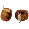
Start from the real current waveform
Define switching frequency, ripple current and peak transient current at the design stage. A nominal ten-microhenry value is insufficient without defining its tolerance and the bias-current condition.
Compare saturation current against peak current, not merely average load. Peak current may saturate the magnetic material even while average current appears acceptable. Check RMS current and winding temperature rise under sustained operation.
Saturation, DCR and loss
Review DCR because a small resistance difference matters at high current. DCR losses grow with the square of current and need to be assessed with copper temperature. Evaluate inductance tolerance across current and temperature, not only at no load. Check mounting orientation, footprint, terminal size and soldering requirements. Terminal footprint and core height are fixed by the assembly constraints, not marketing photography.
Record stray field and potential coupling to nearby sensors or communication traces.
Ask for loss curves or test results relevant to the intended frequency. Stray field can disturb a nearby sensor or communications trace, especially in a crowded power stage. Thermally test the inductor in the closed product, not just on an open bench. Define insulation and creepage needs for the actual power stage. Loss curves should refer to the relevant switching frequency and temperature, not only a generic catalogue test.
Approve samples and documentation before custom tooling or large production runs. The team may know the sales description but still cannot decide whether saturation or winding heat outside the nominal bench condition.
