CNC Insert Chipbreakers Explained: Finishing, Medium & Roughing Geometries
Author : Surya makeyoueasy | Published On : 22 Oct 2026
Introduction
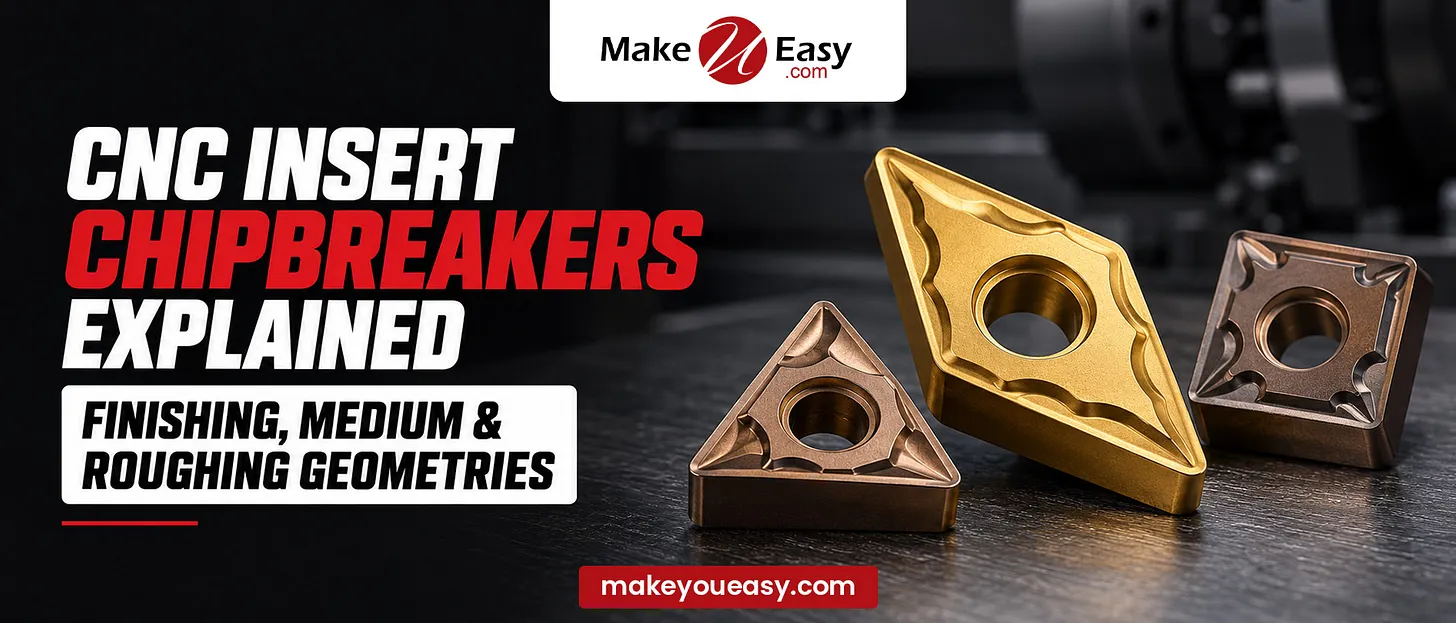
In CNC turning, selecting the correct carbide insert is only part of achieving efficient machining. The chipbreaker geometry also plays a major role in controlling chip formation, surface finish, cutting forces, and tool life.
A chipbreaker is a specially designed groove or profile on the insert’s rake face. It curls and redirects the chip so it can break into manageable pieces instead of forming long, continuous strands.
CNC turning insert chipbreakers are commonly grouped into three categories: finishing, medium, and roughing geometries. Each is designed for a different combination of feed rate, depth of cut, and cutting-edge strength.
Understanding these differences helps machinists improve productivity, reduce chip-related interruptions, and select the right insert for each operation.
What Is a CNC Insert Chipbreaker?
A chipbreaker is a geometric feature formed on the top surface of a cutting insert. As the insert removes material, the chip flows across this surface and interacts with the chipbreaker’s shape.
The groove encourages the chip to curl tightly. When the chip experiences sufficient bending stress, it breaks into shorter segments.
The exact result depends on several factors, including:
-
Feed rate and depth of cut
-
Workpiece material and chip ductility
-
Cutting speed and coolant conditions
-
Insert geometry and chipbreaker design
-
Toolholder rigidity and machining stability
A correctly selected chipbreaker can improve chip evacuation, prevent chips from wrapping around the workpiece, and reduce the risk of surface damage.
Types of CNC Insert Chipbreakers
1. Finishing Chipbreaker Geometry
Finishing chipbreakers are designed for light cuts, lower feed rates, and applications where surface quality is important.
Their cutting edges are generally sharper, helping reduce cutting forces when removing small amounts of material.
Key characteristics:
-
Designed for low feed rates and relatively shallow cuts
-
Sharp cutting edge with low cutting resistance
-
Good potential for surface finish and dimensional accuracy
-
Suitable for finishing passes and light material removal
Typical applications:
-
Final finishing of turned components
-
Precision shafts and bushings
-
Thin-walled components requiring lower cutting forces
-
Components with tight surface-finish requirements
Limitation: A finishing geometry may struggle with heavy cuts. Excessive cutting loads can cause edge chipping, premature wear, or insert breakage.
2. Medium Chipbreaker Geometry
Medium chipbreakers provide a balance between cutting-edge strength, chip control, and surface quality. They are commonly used for general-purpose turning and semi-finishing.
Their operating range is usually broader than that of dedicated finishing geometries, although the actual range depends on the insert manufacturer and model.
Key characteristics:
-
Balanced cutting-edge sharpness and strength
-
Versatile performance across a range of feed rates and depths of cut
-
Suitable for general production machining
-
Good balance between productivity and surface quality
Typical applications:
-
General CNC turning
-
Semi-finishing operations
-
Components requiring multiple machining passes
-
Production environments machining a variety of workpieces
Limitation: A medium geometry may not provide the best performance when cutting conditions are extremely light or when heavy roughing loads demand a stronger edge.
3. Roughing Chipbreaker Geometry
Roughing chipbreakers are designed for heavier cutting conditions, where material removal rate and cutting-edge durability are priorities.
They commonly use a reinforced cutting edge and a chipbreaker profile suited to thicker chips and higher cutting loads.
Key characteristics:
-
Stronger edge preparation for demanding cuts
-
Designed for higher feed rates and larger depths of cut within the specified operating range
-
Suitable for heavy material removal
-
Can be appropriate for certain interrupted cuts when supported by the recommended insert grade and geometry
Typical applications:
-
Removing excess stock from raw material
-
Heavy external turning
-
Rough machining of forged or cast components
-
Production operations prioritizing metal removal rate
Limitation: A roughing geometry may not cut effectively at very low feed rates or extremely shallow depths. It can produce poor chip control, increased cutting forces, or an unsatisfactory finish if used outside its intended range.
Finishing vs Medium vs Roughing: Comparison Table
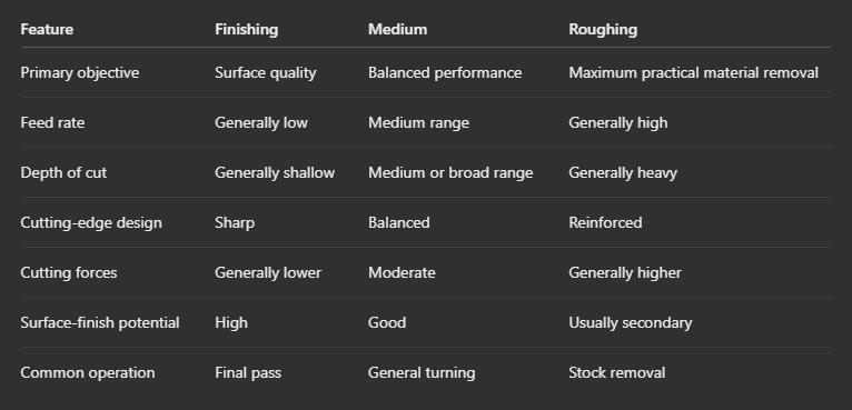
Important: These categories describe general design intentions, not universal cutting parameters. Always use the manufacturer’s recommended feed-rate and depth-of-cut range for the exact insert, material, and operation.
How Chipbreaker Geometry Affects CNC Machining
1. Chip Control
The correct chipbreaker encourages chips to curl and break into manageable lengths. Poor chip control can lead to long strands, chip entanglement, and interruptions during machining.
2. Surface Finish
Finishing geometries often help achieve a better surface because their sharper edges can cut cleanly at light feeds. However, surface finish also depends on nose radius, feed rate, cutting speed, tool condition, and machine stability.
3. Tool Life
A chipbreaker that matches the cutting conditions helps distribute cutting loads appropriately. An unsuitable geometry can lead to edge chipping, excessive wear, or unstable chip formation.
4. Cutting Forces and Machine Load
Sharper geometries generally reduce cutting resistance, while stronger edge preparations can withstand demanding loads. The correct balance depends on the workpiece, machine power, and setup rigidity.
5. Productivity
Choosing the right geometry helps maintain consistent machining, reduce chip-clearing interruptions, and support reliable production cycles.
How to Select the Right Chipbreaker
Follow these practical steps when choosing a CNC turning insert:
Step 1: Identify the operation. Determine whether the tool will perform finishing, general turning, or heavy roughing.
Step 2: Check the workpiece material. Steel, stainless steel, cast iron, and heat-resistant alloys have different chip-forming and cutting requirements.
Step 3: Confirm feed rate and depth of cut. Check that both parameters fall within the chipbreaker’s recommended operating window.
Step 4: Evaluate cutting-edge strength. Consider continuous or interrupted cutting, workpiece scale, machine rigidity, and the possibility of impact loads.
Step 5: Check chip formation during a test cut. Observe chip shape, cutting sound, surface quality, spindle load, and insert wear. Change one major parameter at a time when troubleshooting.
Step 6: Follow the manufacturer’s recommendations. Chipbreaker codes and performance ranges vary between manufacturers, so do not assume that similarly named geometries are interchangeable.
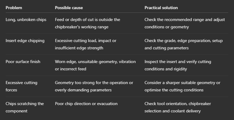
Common Chipbreaker Problems and Solutions
Why Choose MakeYouEasy?
At MakeYouEasy, machining knowledge helps users better understand CNC tooling, cutting-tool selection, and manufacturing processes. Learning how finishing, medium, and roughing chipbreakers differ can help machinists make more informed tooling decisions and improve their machining workflow.
Conclusion
Finishing, medium, and roughing chipbreakers are designed for different cutting conditions. Finishing geometries prioritize clean cutting at light feeds, medium geometries offer versatility for general turning, and roughing geometries focus on edge strength and demanding material removal.
The best choice is not necessarily the strongest or sharpest insert. It is the geometry whose operating range matches the workpiece material, feed rate, depth of cut, and machine setup.
Match the chipbreaker to the actual cutting conditions to improve chip control, surface quality, tool life, and machining efficiency.
FAQs
1. What is the main purpose of a CNC insert chipbreaker?
A chipbreaker curls and breaks chips into manageable lengths to improve chip evacuation and machining safety.
2. What is the difference between finishing and roughing chipbreakers?
Finishing chipbreakers are designed for light cuts and surface quality, while roughing chipbreakers are designed for heavier cutting loads and greater edge strength.
3. Which chipbreaker is best for general CNC turning?
A medium chipbreaker is often a practical starting point for general turning, provided its recommended cutting range matches the application.
4. Can I use a roughing chipbreaker for finishing?
You can use one only if the cutting conditions fall within its specified range, but a dedicated finishing geometry may provide better results for light cuts.
5. Why is my CNC insert producing long chips?
Long chips can result from unsuitable chipbreaker geometry, feed or depth of cut, workpiece material, or other cutting conditions.
Popular Search Keywords
CNC insert chipbreakers, finishing chipbreaker geometry, medium chipbreaker insert, roughing chipbreaker geometry, carbide turning inserts, CNC turning insert selection, chip control in CNC machining, CNC insert geometry, chipbreaker selection guide, turning insert cutting parameters
